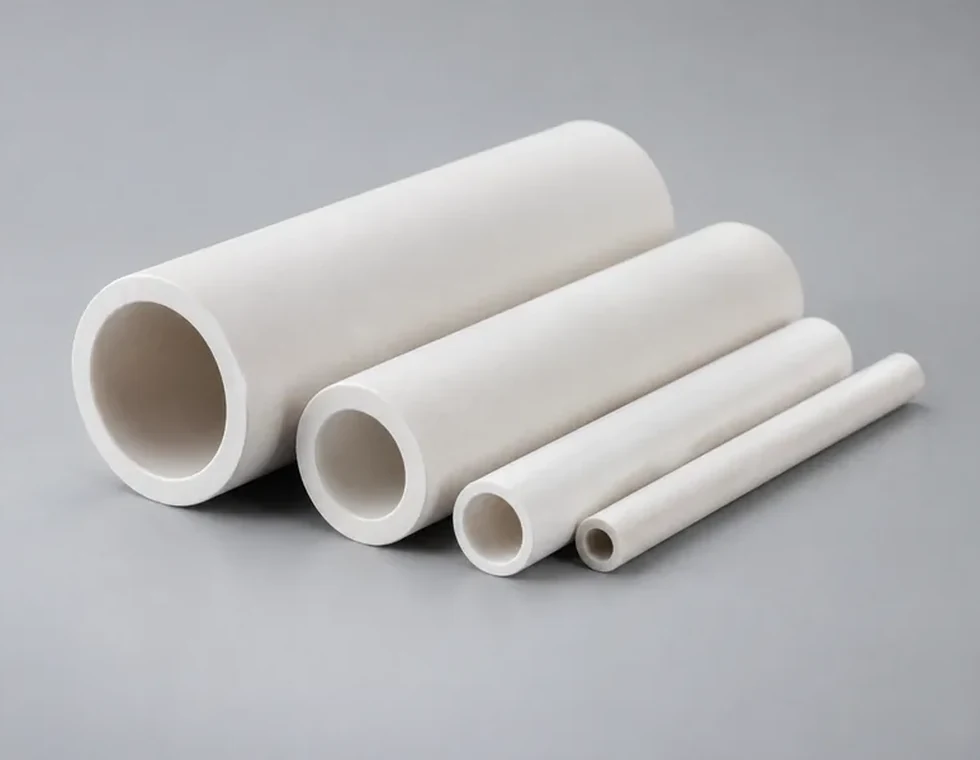
Tubular Feedthrough
Tubular Ceramic Feedthrough Insulators
Precision ceramic tubes used to isolate conductors or terminals passing through housings, fixtures and electrical assemblies.
Precision ceramic feedthrough components for electrical isolation, conductor support, vacuum interfaces and sealed equipment. Feedthrough performance depends on the ceramic bore, conductor clearance, flange or mounting geometry, metallized interface and the way mechanical and thermal loads pass through the assembly.
A feedthrough ceramic is part of a complete interface. Conductor type, electrical potential, atmosphere, mounting method and seal requirement should be considered together.
For conductors, pins or terminals passing through a housing while the ceramic maintains electrical separation from surrounding metal.
For vacuum equipment where the ceramic supports an electrical or mechanical passage through the chamber boundary.
For gas, fluid or controlled-atmosphere equipment where the feedthrough region must support both isolation and a stable sealed interface.
For feedthrough assemblies operating near heaters, furnaces or thermal processes where insulating geometry must remain stable at temperature.
Feedthrough ceramics can be manufactured around conductor geometry, mounting structure, sealing method and application-specific interface requirements.
Precision ceramic tubes used to isolate conductors or terminals passing through housings, fixtures and electrical assemblies.
Feedthrough ceramics with shoulders or flanges for controlled location, mounting and interface support inside a larger assembly.
Ceramic parts with defined interface areas that can be evaluated for joining into metal feedthrough or sealed electrical assemblies.
Precision ceramics for vacuum hardware where controlled dimensions, stable insulating geometry and assembly alignment are important.
Custom multi-passage ceramic components for assemblies that require several conductors or channels to remain positioned and electrically separated.
Drawing-based feedthrough ceramics with custom bores, shoulders, grooves, sealing faces and mounting features for specialized equipment.
Feedthrough reliability depends on the complete interface. Bore clearance, ceramic wall thickness, conductor alignment and the connection to the surrounding structure should be evaluated together.
The relationship between bore size and conductor diameter affects positioning, electrical spacing and assembly behavior.
Ceramic length, wall geometry and surface path should reflect the electrical and environmental conditions of the feedthrough.
Flanges, shoulders, metallized zones and sealing faces determine how the ceramic is located and integrated into the surrounding hardware.
Temperature change can shift the relationship between ceramic, conductor and metal housing, especially in joined assemblies.
A feedthrough drawing should make the electrical path, conductor position and mounting method clear. This helps keep dimensional control focused on the interfaces that determine assembly performance.
Feedthrough ceramics should be selected around dielectric function, thermal exposure, joining method, process environment and the mechanical support provided by the surrounding assembly.
A practical choice for many electrically insulating feedthrough components requiring dimensional stability and broad industrial compatibility.
Other ceramic systems can be evaluated when thermal conductivity, dielectric behavior, purity or process compatibility becomes the main design driver.
Defined ceramic surface areas can be evaluated for applications that require joining to metal hardware or a sealed assembly structure.
Conductors, flanges and housings should be considered together with the ceramic so temperature, load and joining conditions remain compatible.
Feedthrough issues often develop at the interface rather than in the ceramic body itself. Good design should protect the insulating path, alignment and joined region at the same time.
A thin ceramic wall around conductors, shoulders or local features can create mechanical weakness and reduce margin around critical insulating areas.
Off-axis assembly can introduce side load or reduce clearances. Bore position, concentricity and mounting datums should be defined from the real assembly.
In ceramic-to-metal feedthroughs, differing thermal response between materials can load the interface during temperature cycling. Joint geometry should account for this behavior.
Ceramic feedthrough components are used where electrical isolation must be combined with controlled passage, mounting or sealing through an equipment boundary.
Feedthrough ceramics used to support conductors or terminals passing through vacuum chambers and controlled-atmosphere hardware.
Precision insulating components for electrically controlled assemblies where dimensional stability and clean interfaces matter.
Feedthrough insulators used to carry electrical connections through furnace walls or thermal equipment while maintaining isolation.
Ceramic interfaces used to position and isolate electrical conductors in measurement, monitoring and analytical assemblies.
Feedthrough components used where conductors must pass through metal housings, barriers or mounting structures without electrical contact.
Drawing-based feedthrough ceramics for specialized vacuum, process, electronic and industrial equipment.
Feedthrough inspection should focus on the bore, insulating geometry and interface relationships that determine conductor position, mounting accuracy and final assembly performance.
The most useful feedthrough RFQs show the conductor, ceramic and housing relationship together. This makes it easier to evaluate bore clearance, insulation path, mounting geometry and interface requirements correctly.
They are used to support and electrically isolate conductors, pins or terminals that pass through housings, barriers, vacuum chambers or high-temperature equipment.
Yes. Feedthrough ceramics can be evaluated from 2D drawings or 3D models that define the bore, outside geometry, mounting features, interface areas and application conditions.
Yes. Defined metallized interface areas can be evaluated for applications that require integration into ceramic-to-metal or sealed feedthrough assemblies.
They help maintain consistent conductor clearance, reduce unintended side loading and keep the electrical and mechanical interfaces positioned as designed.
Please provide the drawing, bore and conductor dimensions, material preference, electrical requirements, mounting or joining details, operating environment and expected quantities.
Send your drawing and assembly conditions for an engineering review focused on insulation, alignment and interface stability.